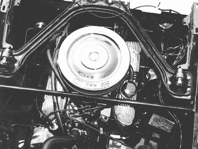
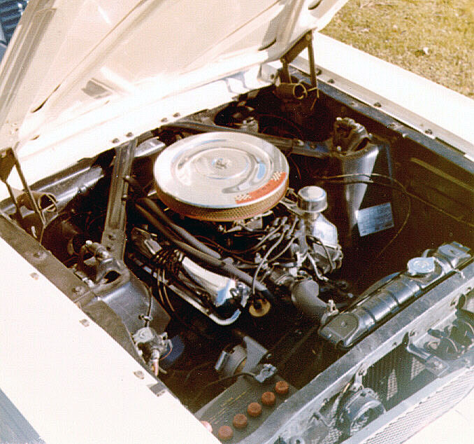
Hi Everyone
Before I cutoff the excess length of heater hose, could someone please post a pic of what is the correct positioning.
(Just wanting to know whether both hoses run along the rocker cover)
Thanks
Rohan

Hi Everyone
Before I cutoff the excess length of heater hose, could someone please post a pic of what is the correct positioning.
(Just wanting to know whether both hoses run along the rocker cover)
Thanks
Rohan
That's a great question and I have been looking for the answer myself. You might want to take a look at the factory Assemby manuals produced by Osborn. In the pictures I was recently looking at for hipos they show one of the hose sections installed along the top of the intake manifold and the other beside it held in place with two aluminum ties. This is contrary to the commonly seen pair of hoses routed through a rubber-tire hose strap suspended from the cowl brace. My car has the two dimples in the cowl brace, but they were never drilled for the strap. I'm seeiking the same answer you are. At this point I'm going to default to the Osborn illustration.
A mistake a lot of restorers do, is to
put the hoses the wrong way through
the firewall and consequently to the heater.
The waterpump hose goes through the upper hole
at the firewall and the intake hose goes
through the lower.
/Bo
There seems to be some variability in hose length. The pic below is a 1965 GT350 Shelby American publicity photo. However, the three 66 GT350 test mag articles I have show both hoses shorter and running between the rocker cover and intake manifold.
[Blocked Image: http://1965gt350mustang.com/temp/GT350hose.jpg]
Hi Dave,
Can you send me the photo that you published
here to my home email address, please.
I believe it's a bit larger than shown here
including the radiator etc.
Thanks,
/Bo
 Quote from round2K
In the pictures I was recently looking at for hipos they show one of the hose sections installed along the top of the intake manifold and the other beside it held in place with two aluminum ties.
Sounds like a pic of my Kar? As I did mine this way when I saw pics of another one like that in one of my many hardcover Mustang books.
Now I decided to use the aluminum ties for conveinence, not corectness. Running tri-power I wanted to make my life easy for adjusting valves.
Now when I posted pics of my engine compartment, Mr. Turner pointed out the incorrect routing and the aluminum straps. I was not bothered by it, as I explained why I did it the way I did. My Kar isn't concours, so I wasn't worried.
Here's a couple of the pics from before:
[Blocked Image: http://home.comcast.net/~ruspen/Pics/Ins_Engine2.JPG]
[Blocked Image: http://home.comcast.net/~ruspen/Pics/Engine_Compartment2_40.JPG]
[Blocked Image: http://home.comcast.net/~ruspen/Pics/Engine_Compartment_40.JPG]
I just noticed this pic and remembered this post - figured it might be of interest.
It is from this site: Pete Ruff's Previous 1965 K 2 2
It's an early San Jose car.
http://www.myruffhouse.com/1965_mustang_22.htm
[Blocked Image: http://www.myruffhouse.com/Mustang-5.jpg]
Don’t have an account yet? Register yourself now and be a part of our community!